System Architecture
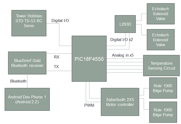
Our electronics plan was to keep everything as simple as possible. If something was not readily available, only then would be buy it. Based on our original goals and impressions for what would work, we created the system architecture above. Using the USART peripheral, we would send serial commands over Bluetooth to the Android phone via the BlueSmirf peripheral. Separately, the analog to digital converters on the microcontroller (uC) would read the values from the temperature sensors which would enable it to detect fires. In addition, the PWM outputs are used to control the two Bilge pumps, which are just DC motors. Finally, three (although the diagram only shows 2) digital I/Os were to be used to control the solenoid valves. Since the solenoid valves require more current than the uC can supply, the L293D H bridge driver is used to step up the current output.
While there was nothing wrong (electrically) with this setup, we learned towards the end that using the valves would not be feasible. Our redesign then involved using an RC servo to clamp down on a latex tube as a valve. In addition, we found that water would not choose to run to the turret if it could flow out the back. Therefore, we only required two more RC motors to be added to our system. This did not add too much electrical complexity, but forced a rewrite of the software.
We also ended up getting rid of the analog temperature sensors as we could not feasibly integrate them with the rest of our boat.
Therefore, our revised system architecture for the electronics is below. It reflects the changes noted above, as well as a microcontroller change. We swapped out the PIC19F4550 near the end for a PIC18F2455 as we wanted to save some space.
